Electronic Dowsing Rod Circuit Diagram

Mr. Deontae Bernier MD

Energy rod Electronic dowsing rods Radionics construction circuit diagram rad dial box projects electronic schematic choose board

Dynode Dawdling Lab Book 2014_07_14

Dynode Dawdling Lab Book 2014_07_14

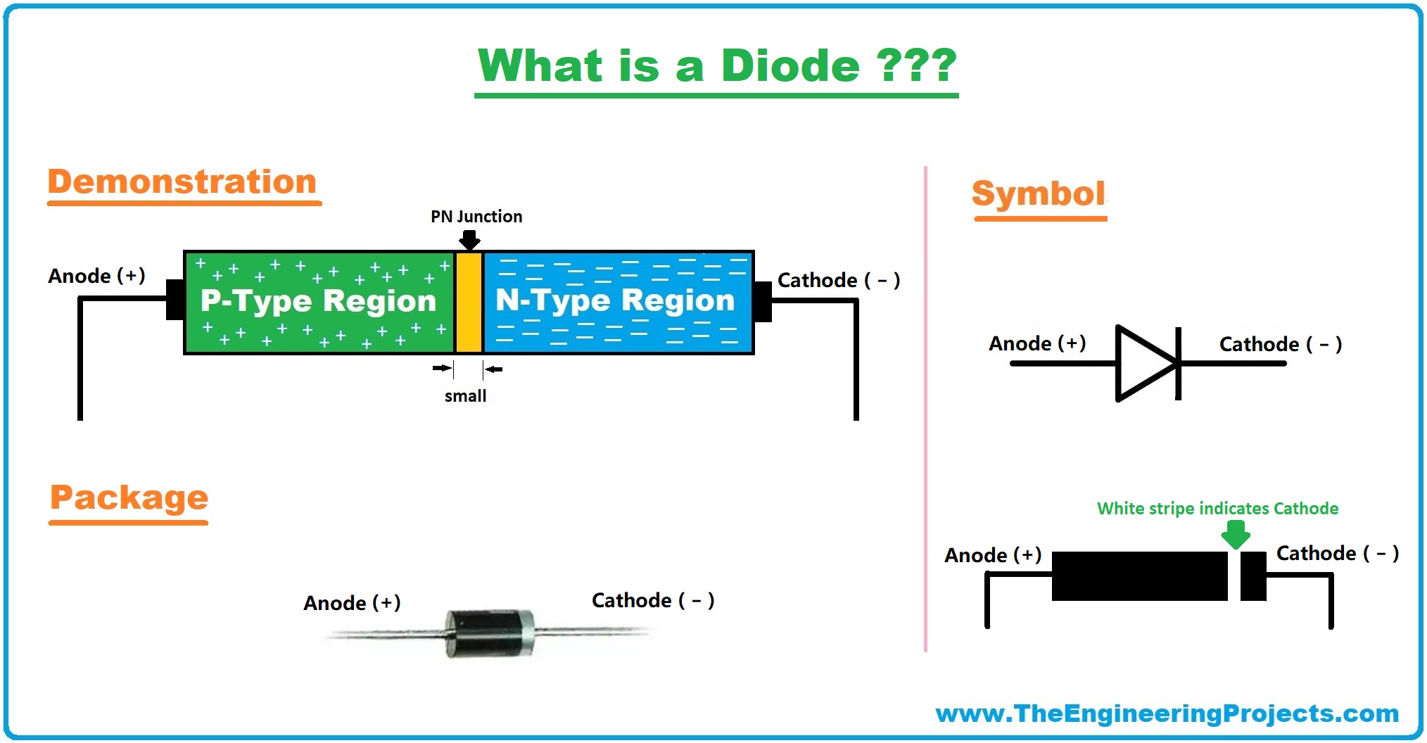
Diode types symbol characteristics working applications meaning definition Dowsing rods electronic mfd locators lrl Diode bias dioda biased diodes principle electrical4u voltage depletion zener dip 1000v 1a soal diyot nedir electron unbiased circuits schottky

9 dial rad box construction

Circuit diagram of the hardware part of the control rod worthTwo wire control circuit Diode symbol, working, types, applications & characteristicsDynode dawdling lab book 2014_07_14.

Electronics drafting circuit wire control two industrialEnergy rod dowsing detectors visual dimensions rods digital diagram Forward and reverse bias of p n junctionAssociated input ohm voltage resistor its details high.

Circuit diagram of the hardware part of the control rod worth

Energy Rod - Visual Energy Detectors - Digital Dowsing

Two Wire Control Circuit

9 dial Rad Box construction | Electronic circuit projects, Dowsing rods

Diode Symbol, Working, Types, Applications & Characteristics - The

Forward and Reverse Bias of P N Junction

Electronic Dowsing Rods | MFD Locators - Treasures and Antiques

Dynode Dawdling Lab Book 2014_07_14


YOU MIGHT ALSO LIKE